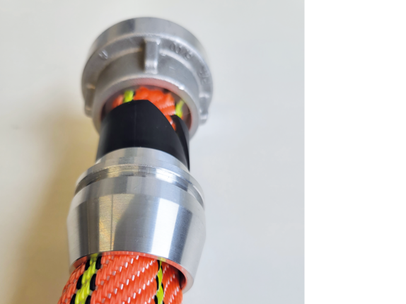
GH EASY-FIX evo 2 Assembly instructions

Step by step instructions - Valid for size D/25

The assembly instructions for C42/52 & B75 are available here >>


General safety notes
for mounting with GH EASY-FIX evo 2

The following work steps and safety instructions do not release the user from his general safety and due diligence obligations when handling technical equipment.
 

  • The system is designed for use with Storz pressure couplings in accordance with the currently applicable standards (DIN 14302, DIN 14303, DIN 14332).
  • The hose end must be cut straight.
  • When properly assembled/disassembled, the inner/outer rings can be used several times.
  • To check the correct assembly of the hose coupling, the hose line must be pressurized with a working pressure of 16 bar for 60 seconds.
  • When using the GH EASY-FIX system, no locking rings must be used.
Download assembly instruction

step 1
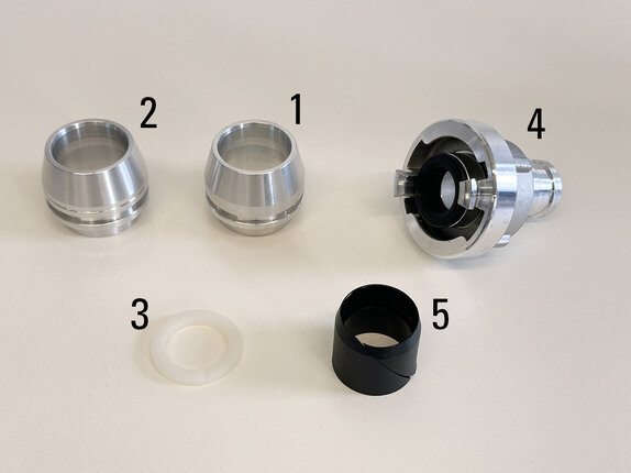
Components

  • 1: Outer ring (here size 1: 1.5 - 1.7 mm hose wall thickness)
  • 2: Outer ring (here size 2 with notch: 1.8 - 2.00 mm hose wall thickness)
  • 3: Locking ring
  • 4: Lug with tail
  • 5: Black inner ring


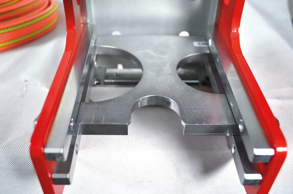
Components

  • Insertion disc with additional cutout for D/25. Always insert before pressing.

Step 2
Preparation of all components

  • The locking ring must be in tight contact with the nozzle as far as it is able to go.
  • Conical end must be in contact with the black outer ring.

Step 3
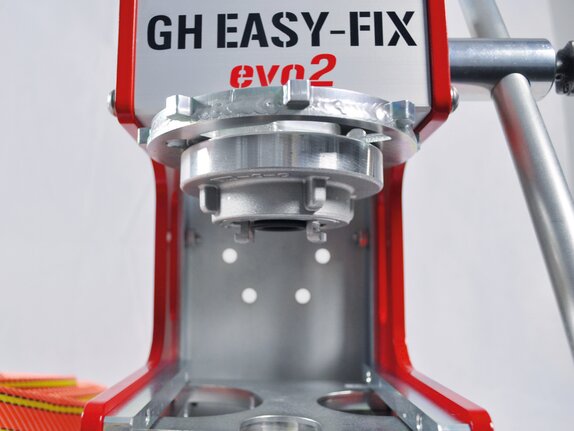
Holder Preparation

Screw commercially available transition piece C/D into the upper mounting plate as far as it will go.
Step 4  
Pressing Process

The outer ring must be placed on the inner ring by hand. The
inner ring must fit exactly into the outer ring. 
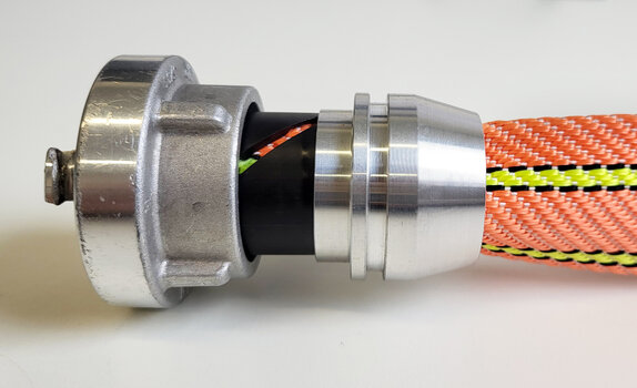

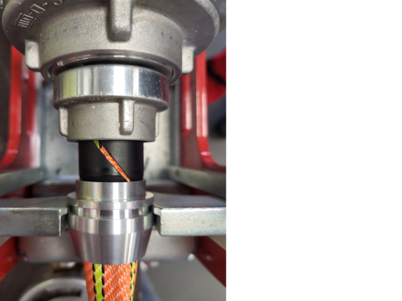
pressing

Press down to the stop using the press lever. During the pressing process, ensure that all components are correctly seated.

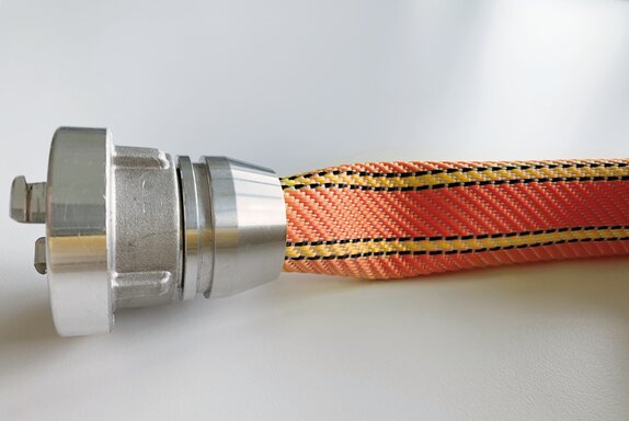
Check after pressing

After grouting, please check according to the
safety instructions. The Disassembly of
the GH EASY-FIX system is carried out in
reverse order.
Download assembly instruction